Search
Complete Guide to Building Your Brewery

$19.95 USD

Support our site by using these affiliate links
Control Panel (Part 1)
STEP 4: Cut holes
You may skip this step if building from one of our control panel kits and you opted to have the enclosure pre-punched as we will already have done this work for you.
We need to cut holes on the door, top, and bottom of the enclosure to attach the various controls and other parts.
 Most industrial components come in various standardized sizes. This makes it much easier to replace components (if required) as you won't need a whole new enclosure if the replacement component comes from a different manufacturer. Everyone uses the same size cutouts.
Standard industrial controls sizes (for whatever reason) are always indicated in metric units, usually millimetres (mm). For this reason you'll find that we often mix imperial and metric units (such as inches and millimetres) as we want to stick with the standard terms that are used in industry whenever possible when describing controls. For example, people will talk about a "22mm switch", not a "0.86614 inch switch".
With the exception of the Amp and Volt meters, everything on our control panel uses standardized sizes. Our PID controllers and timer are DIN 1/16 size which requires a 45x45mm panel cutout. The Amp and Volt meters require a 71x39mm cutout (non-standard sizing).
To create the square and rectangular holes required for these devices, use a hand drill or drill press with a high speed steel (HSS) drill bit to first drill holes in the corners and then cut between the holes using a jigsaw with a fine metal blade. Use a metal file to smooth down all rough edges and corners.
DIN 1/16 punches are available too and are much easier to use, but expect to pay an arm and leg for them. They typically cost over $500 which works out to $125 per hole! At that price we'd rather just use a little more elbow grease to get the job done.
DIN sizes (from left to right): 1/4, 1/8, 1/16, and 1/32.
We use the DIN 1/16 size for our PID controllers and timer.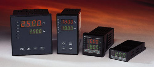
For industrial switches, pushbuttons, and indicator lights, the most common sizes are 22mm and 30mm. This size represents the panel hole diameter required.
22mm devices cost less and require less space. 30mm devices are regularly seen in heavier industrial settings where the panels are often used by gloved workers so buttons and switches need to be larger. 30mm devices are generally more durable and made to withstand abuse and are, therefore, more expensive.
 For our small panel with controls that are rarely used (relatively speaking), 22mm devices are adequate. The smaller size also suits the other components: 30mm switches and lights would have appeared oddly large next to the small Amp/Volt meters and PID controllers.
You have two options for making these holes:
- RECOMMENDED: Use a GreenLee 1/2" conduit punch to punch out the 22mm diameter hole. (A 1/2" conduit punch actually makes a 7/8" or 22mm hole). This is the recommended method (especially if you do not have a drill press) as it results in a clean and perfectly centered hole with the least amount of work. Refer to Step 4: Punch a hole in the kettle from the Heating Elements section for instructions on how to properly create clean holes using a punch like this.
- Use a GreenLee 36414 1-3/8" step drill bit (avoid cheap knockoffs!) to drill the entire 22mm hole. Make sure to stop when you reach a diameter of 22mm (0.867"). Go slowly and use cutting fluid to avoid overheating the step bit. While a hand drill will work, a drill press makes work considerably easier and more precise as it keeps the step bit from pulling in one direction which can result in holes that are not perfectly aligned. Use a metal file to smooth down any rough edges.
The location and size of the holes are shown in the pictures below. For example, the hole for the blue power light at the top left is centered 2" from the top edge and 1-1/2" from the left edge of the panel.
Use a metal file to create the little notches on the sides of the holes for the Amp and Volt meters (as shown the photos below) to help make insertion easier.
Front door hole location and sizes:
Use a GreenLee 36414 1-3/8" step drill bit to drill the 22m diameter holes.
Make sure to apply cutting fluid as you proceed to avoid overheating the bit.

The temperature probe, heating element, pump, and the main power input receptacle holes will vary in size based on the receptacles you use.
We used a GreenLee 36414 1-3/8" step drill bit to drill ~18mm* diameter holes for the XLR receptacles and then bi-metal hole saws to cut ~45mm*, ~51mm*, and ~57mm* holes.
*WARNING: The hole sizes will vary slightly based on the receptacle brand used. Before cutting, confirm the hole sizes required by measuring the actual receptacles you will be installing.
Insert the receptacles temporarily to mark the locations of the screw holes with a sharpie permanent marker and then drill using high speed steel (HSS) drill bits.
Cutting the receptacle holes:
The size and position of the hole(s) on top of the enclosure depends on the size and number of heat sinks (one or two) that are used. This choice was made earlier.
We use one large heat sink on the top of our control panel so one 7 x 2-1/2" hole was cut. If you chose to use two standard 40 amp heat sinks, two 1-3/4 x 2-1/4" holes are required instead.
To create the rectangular holes use a drill with a high speed steel (HSS) drill bit to first drill holes in the corners and then cut between the holes using a jigsaw with a fine metal blade. Use a metal file to smooth down all rough edges and corners.
The hole on top for our large heat sink is 7 x 2-1/2" and centered: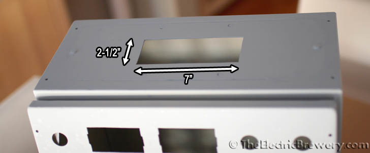
If using two standard 40 amp SSR heat sinks, cut two holes that are 1-3/4 x 2-1/4" in size instead. Center the holes on the top of the enclosure and leave a few inches between them to provide better air circulation around the heat sinks.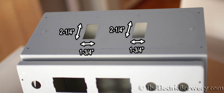
During the design phase of our brewing setup we wanted to keep our options open and therefore cut a hole large enough to accommodate a third SSR. A third SSR would have been required if we had chosen to go with a RIMS (Recirculating Infusion Mash System) setup instead of a HERMS (Heat Exchanged Recirculating Mash System) setup (more information).
Inside of the control panel showing the two SSRs attached to the external heat sink:


