Control Panel (Part 1)
Step 14: Install heat sink/SSRs
You may skip the tapping portion of this step if building from one of our control panel kits as we will already have done this work for you.
In an earlier step you chose whether to install one large heat sink or two smaller 40 amp heat sinks. One or two holes were then cut at the top of the enclosure.
Now we're going to mount the SSRs on the heat sink(s) and then install the heat sink(s) on the enclosure.
Exact measurements will not be possible here as it depends on the heat sink you are using. Instead, we'll show you pictures and instructions based on the large heat sink we used.
 Our large heat sink did not come with any threaded holes for screws so we had to create our own. To do this a tap and die set is required. Inexpensive sets are available for $20-30 USD.
Taps are used for adding threads to holes so that screws can be attached. Taps look like funny drill bits with threads on them (see picture to the left). A die is used for adding threads to metal rods to create screws. Dies look like large nuts with threads in the middle. Taps and dies are typically sold in sets. We'll only be using the tap portion of the set since we only need to create threaded holes. No need to make screws. We can simply buy them!
The SSRs are attached to our large heat sink using two 6-32 x 1/2" machine screws while the heat sink itself is attached to the enclosure using six 1/4-20 x 1" stove bolts. The screw sizes aren't overly important. Use whatever you have handy.
If you chose to go with two 40 amp heat sinks, they already include threaded holes for the SSRs as well as the screws. Two other holes will have to be created however to attach the heat sinks to the enclosure.
Drill a pilot hole first using a drill and high speed steel (HSS) drill bit. Refer to your tap and die set for the correct size pilot hole for the screw size you'll be using. Clean all metal shavings out of the holes and then thread the holes using the correct size tap. Go slowly, turning the tap by hand and let the tap do the work.
The top of the enclosure where the heat sink will be installed.
A pilot hole is first drilled in the heat sink and then threaded using a tap (shown below):
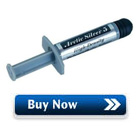
 When the SSR heats up during use, the heat sink will 'wick' away heat. To ensure that the contact between the SSR and the heat sink is as perfect as possible with as little to no air as possible (air is a very good insulator) we use a thick white paste called heat sink compound to fill in any small gaps or imperfections between the two surfaces. Heat sink compound is much better at conducting heat than air, allowing a maximum amount of heat to pass from the SSR to the heat sink.
Apply a very thin layer of heat sink compound to the entire surface of the metal plate on the bottom of the SSR. Use just enough to fill in any possible gaps. Press the two surfaces together tightly and then separate to see if the entire area is covered. If not, apply slightly more and repeat.
Screw the SSR tightly to the heat sink.
Note: Don't worry about the quality or brand of heat sink compound used here. For our use there's little difference.
Apply a thin layer of heat sink compound to the bottom of the SSR and press firmly against the heat sink to ensure complete coverage:
Apply a thin bead of all purpose kitchen/bath silicone sealant around the outside bottom of the heat sink. This will ensure that we create a watertight seal with the outside once it is installed. The GE Silicone I product we use (shown in the picture below) is rated to 400F.
Silicone sealant is used for a watertight seal:
Attach the heat sink to the enclosure using six 1/4-20 x 1" stove bolts:
The large heat sink installed, leaving enough room to carry the control panel by the handles:

Your control panel now looks finished! Unfortunately not much happens when you turn the key to power it up...
Move on now to Building Your Brewery - Control Panel (Part 2) where we'll describe how to install the internal components and provide wiring details.


