Control Panel (Part 2)
STEP 11: Wire up heating elements
 One heating element uses approximately 23 amps of current (out of the 30 amps available in our control panel) so it's important that only one element be active at once. Trying to use two would cause our 30A circuit breaker to trip.
We can't assume that the operator will always turn down the temperature on one PID controller to shut one element off before turning on the other one. No device should be designed such that the power requirements can be exceeded if switches or controls are used in the right (or wrong) order. That would be a poor design just waiting for an accident to happen.
We control which of the two heating elements may be active with the ELEMENT SELECT 3 position switch. It has 3 settings: BOIL, OFF, or HLT. The OFF setting is purposely placed in between the other two to ensure that one element is truly off before the other is turned on. The ELEMENT SELECT switch does not turn on the respective element, it only allows the element to be on if the PID controller/SSR wants it to be on. In other words, the PID controller may be firing the SSR but unless the ELEMENT SELECT switch is also set correctly the element will not receive any power.
Two ELEMENT ON 220V pilot lights are used to let us know when power is being applied to one of the two heating elements. This is an added safety precaution to show us what is going on.
The ELEMENT SELECT 3 position switch is used to control which (if either) of the two kettles can receive power.
The ELEMENT ON 220V pilot lights show us when a heating element is firing.
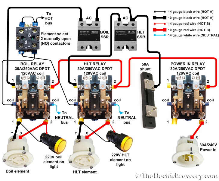
Wire up the components as shown in the diagram below using the wire sizes and colours indicated.
Heating element wiring diagram: 
How it works
The Boil Kettle and Hot Liquor Tank heating elements are fed from the 120V HOT A and HOT B lines for a total (differential actually) of 240V.
When the ELEMENT SELECT 3 position switch is turned to either BOIL or HLT, the switch energizes either the BOIL or HLT relay coil which in turn allows power to pass only to that one heating element regardless of how the PID controllers are set. While 120V may be presented to one side of the heating element through the red HOT A line, current will not flow (and therefore heat will not be generated) until the entire loop is closed by the relay and SSR pair.
At first glance the BOIL and HLT relays may seem redundant: We use a PID which controls an SSR which in turn tells the element when to fire. So why are the mechanical relays needed at all? Why don't we simply use the ELEMENT SELECT 3 position switch between the PIDs and SSRs instead? The reason is safety: The mechanical relays ensure that there is a complete physical disconnect between both HOT lines and the heating elements when the relay is off. This is important as we will often be working or cleaning one kettle while the other is operational.
 Doing something similar with SSRs would require 2 SSRs per heating element (one for HOT A and one for HOT B), but even that would not be 100% safe as SSRs have a small amount of leakage current that flows through at all times, even when the SSR is off. SSRs are also known to fail from time to time and when they do, they tend to fail "closed" meaning that the heating element stays on. The mechanical relays provide us with the peace of mind that when we've turned the element off, there is no possibility of it coming on by accident nor is any side of it energized.
So why use SSRs at all? Why can't we just use the mechanical relays? SSRs are Solid State Relays, essentially switches with no moving parts so they are able to switch as fast as required, often many times per second. Regular mechanical relays are not meant for this amount of switching as the contacts would wear out quickly. Whenever frequent switching is required, SSRs are used instead as we've done here. The three 30A/240V DPDT relays we use are only switched once or twice during the brewing session so they are being used in the way that they are designed to operate.
Whenever power flows to one of the heating elements, the respective ELEMENT ON 220V pilot light (wired in parallel with the element) turns on letting us know that power is being applied. This is an added safety precaution to show us what is going on. The PID controller may be firing the SSR, but unless the respective mechanical relay is also on the ELEMENT ON 220V pilot light will not come on.
Location of the components:
Close-ups:


